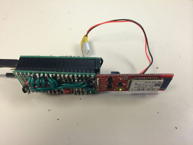
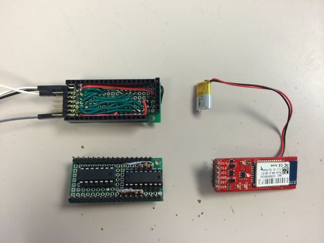
Continuing from part one, which looked at the stuff on the outside of the crutch, this talks about the stuff on the inside: the actual electronics.
You’ll remember in the last post that the first hardware I used was the Adafruit Bluefruit EZ-Key, which is basically a very small Bluetooth keyboard. You can write up switches to it and it will send keyboard signals to the paired computer. It also has a built-in voltage regulator which made it really easy to get started with.
But I knew the Bluefruit would never work in production: it’s too expensive and you can’t reprogram it beyond changing the keystrokes it sends, so I needed to go deeper in to the Maker world.
I found a the Makey-Mate, a module from Sparkfun that is designed to make their “Makey-Makey” device completely wireles. It was prefect for my uses because it could be used on 3.3v or 5v and included battery-charging hardware and a battery connector!
Using the Arduino Micro I wrote code to communicate with the module, read buttons and send keystrokes. However, the Arduino Micro was not a long-term solution either since they are also to expensive to use in a production product. Using tutorials from the internet, I ported the code to the ATtiny84MCU and used that in concert with a priority encoder IC to get around the lack of pins.
This took the projected parts code from $60+ down to a much more reasonable $30. With a little bit of soldering it ended up fitting in the crutch handle quite nicely.
The next version is going to swing back the other way. Although using the ATtiny84 is cost-effective, working with the limited memory and limited I/O has ended up being more trouble than it’s worth in the long run so the next prototypes will go back to using the ATmega328p. That means it won’t need a priority encoder, will have a lot more memory space and it will be compatible with the stock Arduino IDE right out of the box. And if the boards are designed and built smartly, the costs should be about the same.
(Next: Part 3: the stuff in the middle)


